Provided to PEEVA, LLC Prepared by Srinath Natarajan And Dr. Albert H. Titus January 4, 2017
Prototype design for a composite RFID system that can read pet RFID tags that operate at 125 kHz, 128kHz and 134.2kHz. The system has been demonstrated to read all three types of RFID tags while connected to a computer via USB cable. As described below, the system uses a custom designed circuit for reading 125 and 128kHz tags, and a commercial offthe- shelf circuit for reading 134.2kHz tags (which are the ISO standard tags). Read range for thesystem has not been optimized, as this requires proper tuning with an antenna that is designed forthe final system. Antenna design must be done in coordination with package design for the complete tablet and RFID system.
Background:
The RFID low frequency passive tags used in Animal Identification fall under 3 different data protocols namely: Full Duplex or Full Duplex A (FDX or FDX-A), Full Duplex B (FDX-B) and Half Duplex (HDX). The FDX-B uses Amplitude Modulation (AM) with Phase Shift Keying (PSK) and operates at 134kHz carrier frequency. They are frequently used in domestic applications that can accommodate short distance reading.
The HDX animal identification protocol uses Frequency Modulation (FM) and operates at the 134.2kHz band. This method is not widely used for domestic animals. They are used mostly in places where there are large amounts of metal in proximity as the electromagnetic waves- based FDX systems suffer performance loss due to interference in these circumstances. The disadvantages of this method are longer reading time and larger antennas. More informationabout this protocol can be found here:
The FDX-B and HDX systems are based on ISO definitions and hence are global. The FDX or FDX-A is a US based standard for animal identification that uses amplitude modulation with PSK or Frequency Shift Keying (FSK) and operates at 125kHz and 128kHz.
System Design:
The final design has three main blocks (see Figure 1): (a) Module A (125 and 128kHz reader), (b) Module B (134.2kHz reader), and (c) the antenna. Power is supplied via USB ports.
Figure 1. Block diagram of the RFID reader system
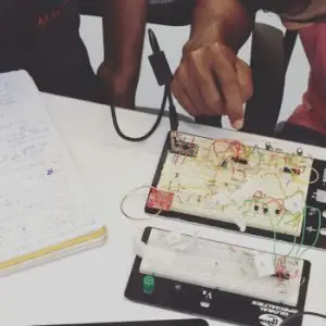
(a) The 125 and 128kHz readers are combined into one custom circuit. This circuit had been breadboarded and demonstrated to read unencrypted tags. It uses an Arduino Pro mini (ATMEGA328) microcontroller to control tag communication and interfaces with a tablet via any USB port. All parts are specified in the parts list, and a separate file contains the printed circuit board (PCB) layout.
(b) 134.2 kHz reader: This reader is a commercial off the shelf device, RFIDRW-E-USB, which is available from priority1Design. This was tested and shown to read all 134.2kHz unencrypted tags. This board interfaces with a tablet via any USB port. Details on this board are provided here:
(c) Antenna: A single coil antenna is used for transmission and receiving signals to and from the RFID tag. This antenna has been demonstrated to function, but ultimately, a different antenna is necessary for optimizing performance and to fit within the desired packaging.
Module A Details (Custom circuit):
Operation: A 125 kHz square wave is generated by the microcontroller. This square wave is then amplified by a power amplifier that is part of the antenna driver circuit. This amplified signal is delivered to the antenna. The antenna creates an electromagnetic wave at a frequency of 125 kHz. When a tag is present in the near field of the antenna, the transmitting antenna is loaded and unloaded by the tag circuitry to write the data. The resulting signal received at the antenna is fed into a peak detector. The envelope of the signal is low pass filtered to remove the carrier signal.
The data signal is then processed to convert the two frequencies or phases into logic levels. These signals are then decoded from the tags encoding (Manchester or Bi-phase) using the micro controller and the 10-digit alpha-numeral code is sent via the serial interface to the PC or tablet.
We present a working design that incorporates two distinct circuit boards and an antenna that is used to read three different RFID tag types. The deliverables provided will allow continuation of the development of the RFID reader with the inclusion of an app running on a tablet that communicates with the two modules.
Read range and Orientation:
The custom Module A is capable of reading the 125kHz Destron tag and the 128Khz Trovan tag and the detection was demonstrated. The read range, which is the distance within which a reader is able to pick up a tag, is generally short when reading micro-chipped animal tags as the antennae of such tags are very small. The read range of Module B is about 1.5 inches. The read range of the custom circuit is approximately 0.25 inches. Addressing one or more of the following factors can improve this:
- Using a larger antenna that has a lower internal resistance (the antenna used for demonstration has an internal resistance of 47 ohms). For example, the RFIDCOIL-250A available from priority1design.com.au is one option for a low impedance coil antenna.
- Increasing the power driven to the antenna (simulations show that with a better matched,
lower impedance antenna, drive powers of over 4W peak are possible). - Adding a core to the antenna: A solid core antenna will greatly improve read range as the
core will enhance the field strength, but this adds weight. However, as stated previously, the final antenna should be designed with packaging in mind.
Orientation is always an issue with the small pet RFID tags, so positioning and alignment of the reader with the tags will likely be necessary. This is true with all readers.
Tablet Integration:
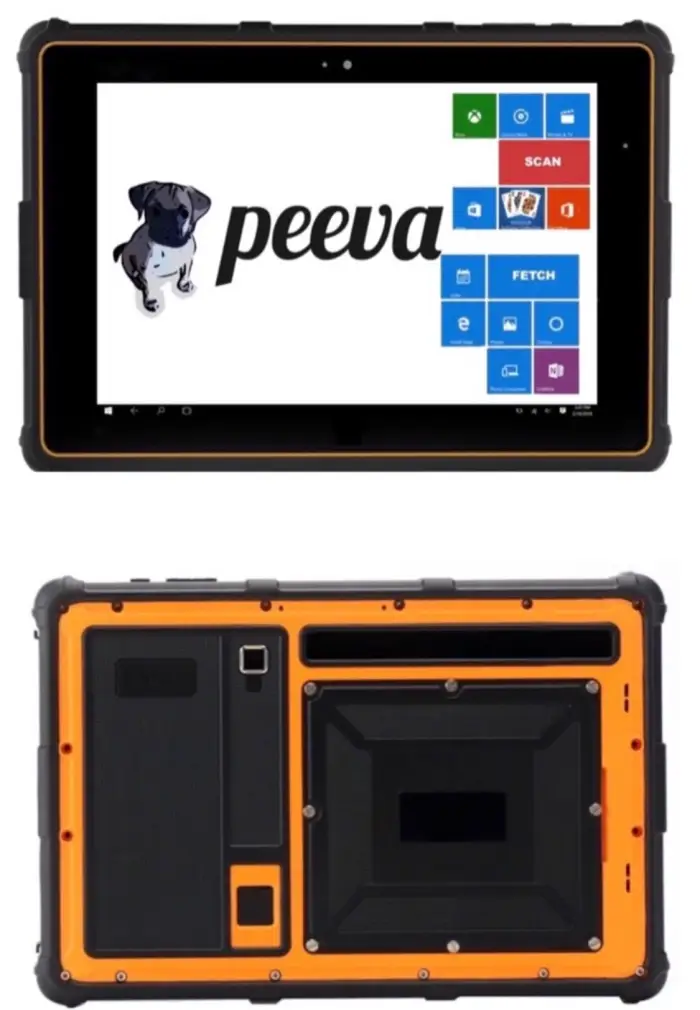
It is suggested that the fabricated and integrated RFID reader boards be packaged with the tablet in a non-ideal package for demonstration and testing purposes. Such a package could be designed easily to enclose the tablet and RFID boards and antenna, and 3-D printed in a plastic material. When testing shows this integrated version to function properly, then optimization can allow the case to be made and the custom boards be altered to be smaller (if necessary).
Ultimate Protection for Your Pet
Maximize the utility of your pet’s microchip with Peeva. Our 24/7 phone support lost pet alerts, and medical records ensure your pet is found faster.


