V.3 The Peeva Universal Scanner V3 can read every chip on the market.
Universal Scanner:
This is presented with various proprietary items redacted
The Peeva universal scanner is capable of reading the unique serial data of every transponder available in the market, Transponders that work on different Transmitting frequencies, i.e., 125kHz, 128kHz and 134.2kHz or different encoding schemes. Also, the different parameters required for each method.
For earlier versions, please see
V1
V2
Amplitude Modulation (AM): In amplitude modulation, the amplitude (signal strength) of the carrier wave is varied in proportion to the waveform being transmitted. In our case, we send a carrier signal of the 125kHz square pulse using the EM4095 module as input to the Loop antenna and receive the Amplitude modulated signal from the other end of the antenna, which is of 40-50V amplitude (based on loop antenna design). The reason for using a 125kHz carrier is explained in the Tx Frequency section.
TX(Transmitting) Frequency:
The Transponders/Tag consist of an IC (which has a memory unit and other mixed-signal modules for modulating and encoding the data signal) and a loop antenna with a resonating frequency of 125kHz/134.2kHz. Thereby, maximum power is transmitted when our antenna is resonating at the approximately same resonating frequency of the transponder’s antenna, and the carrier signal’s frequency is also equal to Antenna’s resonating frequency (in our case 125kHz). We practically designed our antenna’s resonating frequency of 125kHz for this reason. We can also design it close to 128kHz/134.2kHz, but there will be a small amount of power loss in that case as our carrier is also 125Khz, that power loss consideration is significant for reading AVID and Trovan transponders efficiently.
Strictly saying, some of the FDX-A transponders like Trovan work at 128kHz, it’s advisable to use a 125KHz antenna instead of 134.2kHz as the FDX-B tags can be read effectively even with a 125kHz antenna. Practically, if we use 134.2kHz antenna, then SNR (signal to noise ratio) is less than the SNR with 125kHz antenna, as the carrier is 125kHz and that loss cause a hard time in reading FDX-A tags, further explanation about this statement is mentioned later in this document. Point to note is that, it might look trivial and as the difference in frequencies is decidedly less from 125kHz to 134.2kHz, practically after testing in the lab, I observed that variation affects the readings.
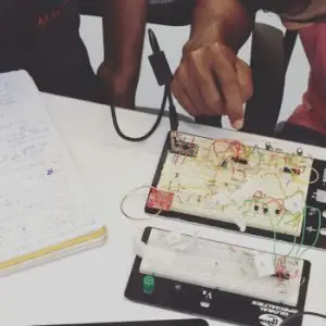
It is transmitting 125kHz, 4Vp-p carrier signal as input to the loop antenna that resonates at 125kHz. The antenna will produce the activation field is perpendicular to the antenna, so we place the transponder as shown in figure 1.
Loop antenna and transponder while reading
When we place the transponder in the EMF range of the antenna, the transponder’s antenna gets powered up by the phenomenon of mutual induction. Once the capacitor inside the transponder gets enough charge, it will activate the microchip and eventually the data is transmitted from the microchip to its micro-antenna, which is then transmitted back from the transponder onto the transceiver antenna, thereby changing the amplitude of the original carrier concerning the data signal (modulating signal).
BIT Encoding/Decoding:
After the received data signal is demodulated, we perform the BIT level decoding. There are usually two types of BIT level encoded data that we can observe among FDX-A and FDX-B family of chips, which are mentioned below.
Phase-shift keying: Phase-shift keying (PSK) is a digital modulation process which conveys the data by changing (modulating) the phase of the reference signal (carrier wave). PSK uses a finite number of phases, each assigned a unique pattern of binary digits. Usually, each phase encodes an equal number of bits. Each pattern of bits forms the symbol that is represented by the particular phase.
Frequency-shift keying: Frequency-shift keying (FSK) is a frequency modulation scheme in which digital information is transmitted through discrete frequency changes of a carrier signal. The simplest FSK is binary FSK (BFSK). BFSK uses a pair of discrete frequencies to transmit binary (0s and 1s) information. With this scheme, the “1” is called the mark frequency (fm=f0/8=15.6kHz) and the “0” is called the space frequency (fs=f0/10=12.5kHz).

Data Encoding:
Mid-bit Binary PSK/BPSK/MDBP BPSK (also sometimes called PRK, phase reversal keying, or 2PSK) is the purest form of phase shift keying (PSK). It uses two phases which are separated by 180° and so can also be termed 2-PSK.
MDBP decoding pattern
Manchester code (also known as phase encoding, or PE) is a line code in which the encoding of each data bit is either low then high, or high then low, for equal time.
Manchester decoding pattern
Non-return to zero (NRZ): A non-return-to-zero (NRZ) line code is a binary code in which ones are represented by one significant condition, usually a positive voltage, while zeros are represented by some other significant condition, usually a negative voltage, with no other neutral or rest condition.
About ISO and non-ISO standards:
We can categories the whole animal microchip industry into 2 different standards, ISO and Non-ISO standard. Well, the majority of the animal microchips in the market are ISO FDX-B chips (~54%, based on Prashanth’s data log collected from Vet Data), the rest are Non-ISO chips. A better insight about the ISO chips and several modulations, decoding are well documented in the ISO document. I have provided a brief abstract about it concerning the hardware.
Note: The HDX transponders are only used in Livestock and not in the pet industry, so we ruled out its hardware implementation from the rest.
ISO Standard transponders (FDX-B):
The transponders have an inbuilt antenna of 134.2kHz; when we transmit the activation field (by transmitting the 125kHz carrier signal over to the antenna’s input terminal), the transponder will transmit its code during that activation period. Based on the ISO document and the experiments performed in the lab, the FDX-B transponders use a modified DBP encoded sub-carrier, which is amplitude modulated onto our 125kHz carrier signal.
The duration of each data bit is equal to 32 activation field cycles, thereby bit rate is 4194 bit/sec, as shown below.
Data structure
Data pattern of FDX-B at a bit level
Non-ISO (FDX-A):
The Non-ISO transponders are the FDX-A standard. It is further divided into regular FDX-A and FDX-A FECAVA version. The FDX-A FECAVA version is manufactured by only Destron; the other regular FDX-A version is manufactured by various manufacturers predominantly Trovan, Datamars, AVID.
Modulation – The demodulation is the same as of ISO family, i.e., Amplitude demodulation.
Encoding – The BIT level encoding is FSK, which different frequency versus phase, followed by different types of data level encoding as mentioned in Table 1.
Destron (FECAVA version):
Destron is a non-ISO FDX-A type, which works at 125kHz with Amplitude modulation followed by FSK BIT encoding with mark and space frequencies of fm=f0/8=15.6kHz and fs=f0/10=12.5kHz respectively.
Duration of each binary state is equal to 100 cycles of carrier signal f0, whereby a binary 0 is represented by 50 cycles of f0/10, followed by 50 cycles of f0/8. A binary 1 is represented by 50 cycles of f0/8, followed by 50 cycles of f0/10, shown below is an example for logic 0.
FDX-A Destron FECAVA and HDX ID pattern
Followed by data level encoding in Manchester, thereby, each bit is of ~256us and for logic ‘0’ the signal will be high for the first 128 us followed by low for remaining 128us. Similarly, for logic ‘1’ the signal will be low for the first 128us followed by high for remaining 128us. The identification telegram consist of 48 data bits, 35 bits of it are the actual information bits, the structure of the Destron (FECAVA version) is shown below,
Destron Identification structure
Trovn is non-ISO FDX-A type, works at 128kHz with Amplitude modulation followed by FSK BIT encoding but interestingly, the BIT level encoding is different than usual. There is a change in the phase of the signal at the beginning of every logic 0. Thereby, the transponder sends its message using PSK in the frequency band f0/2.
Practically, the output of demodulated and digital signal processed signal of a Trovan transponder is a sequence of inverted peaks. Technically, at every transition of data from logic 1 to logic 0, there will be a phase shift of 180°. The envelope will stay low for that one carrier cycle; thus we can see a dip, and there is no change in phase when the data logic changes from 0 to 1.
The duration of each bit is 16 cycles of f0, thereby 128us. The data level encoding is BPSK; thus there is a change in phase at every change in the logic level. Thus, we can see a series of dips usually at equal intervals of 16us or above. Thereby, the phase of the actual data changes by 180° at every transition from logic 0 to 1 or vice versa.
For example, if we see 3 continuous dips at an equal interval of time of 16us, using the D-FF I converted those dips into a signal which changes its phase at every dip, shown in figure X. Later on, we manually converted that signal using BP and successfully obtained the data as 101 which matched to the actual data.
Datamars
Datamars is an ISO FDX-B type, which works at 125kHz with Amplitude modulation followed by FSK BIT encoding, similar to Trovan transponders, there is a particular change in the phase of the signal. Thereby, the transponder sends its message using PSK in the frequency band f0/9.
Datamars’ readers are universal pet microchip scanners that can read FDX-B, FDXA/FECAVA, Avid encrypted, and Trovan microchips using 125kHz, 128kHz, and the ISO 134.2kHz frequencies. In addition, Datamars’ transponders are ISO compliant FDX-B types, which operate at 134.2kHz.
AVID (with Encryption)
AVID is a non-ISO FDX-A type, which works at 125kHz with Amplitude modulation followed by FSK BIT encoding with mark and space frequencies of fm=f0/8=15.6kHz and fs=f0/10=12.5kHz respectively. The duration of each binary state is equal to 100 cycles of carrier signal f0, whereby a binary 0 is represented by 50 cycles of f0/10, followed by 50 cycles of f0/8. A binary 1 is represented by 50 cycles of f0/8, followed by 50 cycles of f0/10, shown below is an example for logic 0.
Although, AVID and FDX-B type transponders have the same modulation and BIT level encoding, interestingly AVID’s transponders were not able to be detected using an EM4095 module, while it does for FDX-B transponders. So, I had to pass the received signal through Module 2 which I used for Trovan transponders detection and decoding.
Envelope detector design
Envelope detector schematic
For simulation purpose, I designed a signal source that generates an Amplitude modulated signal with the carrier signal of 125kHz and data signal of 2kHz. When it is passed through the envelope detector, we can see the blue signal which detects the amplitude of the carrier signal (in green) as shown below.
Destron BIT-level decoding:
The Destron bit-level decoding is FSK with mark and space frequencies of f0/8=15.6kHz and f0/10=12.5kHz. So, using the 5th order low pass filter MAX7414, we can achieve attenuation of 100dB/Decade. The cut-off frequency is set at fc=14kHz. We can observe below the signal’s amplitude changes based on its frequency in figure 31.
Destron FSK decoding using LPF
Actual Destron transponder data observed in the lab:
We can observe the actual output of the Destron transponders, thereby both the mar and space frequencies of 15.6kHz and 12.5kHz respectively.
After passing the signal through LPF, we perform further signal processing using peak detectors and Op-Amp based voltage comparator, we will get the final data encoded signal.
Practically, the signal we observe after we demodulate the received AM signal is FSK encoded data. Using the same notation mentioned in the ISO document, thereby, representing H=12 cycles of f0/8= 15.6kHz each cycle and L=10 cycles of f0/10= 12.5kHz each cycle. We can first detect the header, which will be “HLHLHLHLHHHLLLHL” followed by 5 octets and 5 parity bits. Starting from MSB, the first bit is a parity bit followed by octet respectively.
LHHHLHLH- 01110101
HHHHHHLH- 11111101
LLHHHLLL- 00111000
LHLLHLLH- 01001001
HLLHHLLL- 10011000
Now reverse the data as it’s Manchester decoding at the data level, so we have the final data as,
0 111 0101- 000 1010- 0A
1 111 1101- 000 0010- 02
0 011 1000- 100 0111- 47
0 100 1001- 011 0110- 36
1 001 1000- 110 0111- 67
Taking off the first bit(Left most bit above) in each octet as it’s the parity bit. We are left with 7 bits mentioned beside each. Practically, if we take the first 3 bits as 1 decimal digit and next 4 bits as 1 decimal digit in each segment of 7 bits, we have the actual data. For the Destron tag I tested in the lab, the unique serial number is 0A02473667.
Schematic design for FDX-A transponders:
LTSpice based circuit for FDX-A
The FDX-A circuitry has the same AM demodulation circuitry as of FDX-B. The BIT encoding is same as Destron (FECAVA) version transponders that we were able to detect using the same EM4095 module, but the decoding section varies for other FDX-A transponders, thereby Trovan, AVID and Datamars, as shown in figure 32.
After the demodulated received signal is amplified using U1 and U2 to 2.5V range. Interestingly, the signal is hard to read even after that. I connected the demod_out signal through respective Trovan, and AVID circuitry to BIT-level decode the data.
Trovan decoding:
In the case of Trovan, I passed it through the envelope detector formed by D2, C10, and R10. We can now observe the peaks/dips at the output of the envelope detector below.
Technically, at every dip, the value of the data signal is changing from logic 1 to logic 0 and to avoid the circuit from becoming bulkier, we can detect the phase change using the envelope detector itself. Strictly speaking, when the data signal is logic 1/high, the phase remains the same and even the amplitude but when there is a transition of data from logic 1 to logic 0, the phase changes by 180 degrees. Thereby, a dip in amplitude will occur if we observe the amplitude of a PSK modulated data, a better picture about it can be obtained.
I designed the envelope detector and amplifier circuitry such that it can detect that dip in the data signal’s amplitude at every transition of data from logic 1 to logic 0. Below we can observe those relevant dips in the amplitude of the demodulated data signal.
The duration of each bit is 16 cycles of RF/carrier signal (125kHz) which is 128us. Thus, at every dip the phase changes by 180 degrees. So, if we use a DFF with its output Qbar connected back to the input D, giving those dips as the clock input to it. We can observe the 180 phase change in the output signal at every dip; thus we recovered the FSK decoded signal which has a phase change at the rate of f0/2. Next step is the data level decoding, Bi-phase which is done using the Microcontroller.
- Actual Trovan transponder data observed in the lab:
- Actual Trovan output waveform with dips
- Each dip converting phase of the actual signal using DFF
Following the ISO document and manually performing the data level decoding of the bit level decoded data of a real-time Trovan transponder is mentioned below.
The header is logic 0 followed by 7 logic 1 bits as shown below 01111111 followed by the data below after manually doing the BP data level decoding.
00010001000100011101111011101000100011010010110101000100
After the header, every 4th bit is the parity bit which we discard from the actual data, here I mentioned each parity bit in ().
000(1)000(1)000(1)000(1)110(1)111(0)111(0)100(0)100(0)110(1)001(0)110(1)010(0)010(0)
Now, the first bit is 000 followed by each hex bit is the 4bit numerical data. Thus, we have,
000 – 0; 0000-0; 0000-0; 0110-6; 1111-F; 1110-E; 0100-4; 1100-C; 0111-7; 0010-2; 010- Reserved bit.
Thus, the final unique 10-digit number is 0006FE4C72.
AVID (Encrypted):
For AVID decoding, we use the output of Trovan’s peak detector. We can observe the FSK encoded data as shown below.
As there isn’t any such information about AVID decoding and pattern recognition, I contacted a senior engineer and based on his suggestion. I followed a particular procedure to decode the data further.
Once again, we repeat the same procedure used for Destron’s decoding technique, thereby passing the data signal through the 5th order LPF MAX1414 followed by an op-amp based voltage comparator. Thus, the final output we get is the FSK decoded signal. Let’s represent fm= f0/8= 15.6kHz and fs= f0/10=12.5kHz as H and L respectively.
Actual AVID output waveform(FSK encoded)
Assuming a detection frequency pair of one-eighth of the excitation frequency for high tone, and one-tenth of the excitation frequency for low tone, and a symbol interval of fifty times the excitation field period. An excerpt string of 96 characters is to be created from a sampling of 96 consecutive demodulated symbols, coding with the letter “H” for high tone and “L” for a low tone. Ideally, the demodulator should be designed to place no arbitrary limit on the number of consecutive “H” or “L” symbols between transitions. Otherwise, it becomes the source for calculation of the Long Form representation.
Transponders readable by this Standard give a 96 symbol repeating pattern; the method described above makes a 96 symbol excerpt string with a random arbitrary phase orientation.
This string contains 96 Candidate Substrings of length 96 characters each, each of which can be considered an equivalently valid rotated expression of the repeating pattern, but only one of which will be the Long Form Result.
If exactly one of the 96 Candidate Substrings starts with the string “HLHLLLLLLHHHHHH,” that Candidate Substring is the Long Form. If more than one of the 96 Candidate Substrings starts with the string “HLHLLLLLLHHHHHH,” the Candidate Substring value that ranks last in an alphabetical sort, of all the Candidate Substrings that start with the string “HLHLLLLLLHHHHHH,” is the Long Form Result.
If none of the 96 Candidate Substrings starts with the string “HLHLLLLLLHHHHHH,” the Candidate Substring value that ranks last in an alphabetical sort, of all 96 Candidate Substrings, is the Long Form.
Here is an example, made for illustrative purposes and not indicating an observed transponder specimen: Suppose after demodulating, a 96 character excerpt string is built out to make a 191 character “padded excerpt” string which happens to start like this:
“LLHLHLLLLLLHHHHHHLLLHLHLLLLLLHHHHHHH”. The searched-for string “HLHLLLLLLHHHHHH” appears at the beginning of at least two of the 96 Candidate Substrings. In particular, it appears at the beginning of the third Candidate Substring and the beginning of the twenty-first Candidate Substring. If there are no more matches found in searching all 96 Candidate Substrings, the third Candidate Substring will be the
Long Form Result because it starts with “HLHLLLLLLHHHHHHL” which comes after “HLHLLLLLLHHHHHHH” alphabetically. Calculating the Primary Form. The Primary Display Form is to be calculated from the Long Form, by this procedure:
To make the primary form, the first step is to make a copy of the long form result without punctuation, and in the copy, replace each “H” with digit “1” and each “L” with the digit “0”. Then, if the transponder’s long-form result starts with the string “HLHLLLLLLHHHHHH,” replace the first 15 characters of the copy with the digit “0”.
A unique character string for example, “23456789BDFGHJKLMNPQRSTVWXYZ” is to be defined for use as an ordered list of digits to be used in “base-28” conversion in the next step. The characters in the string have been chosen to limit the possibility of undesirable words appearing in the coded result.
The next step is to split the string of 96 characters into four strings of 24 characters each. Taking each of these four strings as a 24 digit binary or base-two representation of a number, replace it with a five-digit base-28 representation of the same number, using the predefined string for the digit set. Then combine the four base-28 representations in order, making a string of 20 characters.
If the long form result starts with “HLHLLLLLLHHHHHH,” replace the 20 character string with a 17 character string made by removing its first three characters. When expressed with the preferred punctuation, first form representation of a transponder reading is a 17 or 20 printable character string with spacing for readability. There are no “0” or “1” digits. The 17 printable character case is distinctive for its lone final character.
Here is an example of the conversion from the Long Form to the original Form for a real specimen transponder. The long form is
“HLHLLLLL LHHHHHHL LHLHLHHL
LHLHLHHH LLHHHLLH HHLLHHHH
LLHLHHLH HHLHLLLH LHLHLLLH
LLLLHLHL HLLLHHHL HHHLHLLLH”,
then the four quarter pieces made after clearing out the first 15 characters would be:
000000000000000001010110 = 86 decimal = 32 in special base 28
010101110011100111001111 = 5716431 decimal = 98BA7 in special base 28
001011011101000101010001 = 3002705 decimal = 4OLRD in special base 28
000010101000111011010001 = 1383889 decimal = 2714H in special base 28
Complete Hardware circuit for the Universal scanner:
Complete LTSpice circuit of the Universal scanner
The circuit in figure 37 is the final hardware circuitry which can demodulate and BIT-level decode both FDX-B and FDX-A type of transponders. After this, the signals are connected as inputs to the Microcontroller, where these data signal is further decoded at data level with the firmware we are developing.
The firmware will be able to send the unique data through serial communication further and eventually to make the reader completely wireless; we are also going to implement a Bluetooth module to the reader.
Ultimate Protection for Your Pet
Maximize the utility of your pet’s microchip with Peeva. Our 24/7 phone support lost pet alerts, and medical records ensure your pet is found faster.